Author: blickadmin

  • Wet Pan Mill + Centrifugal Concentrator: Two-Stage Recovery

    A wet pan mill does one job well: it grinds ore until gold is liberated from the rock holding it. What it cannot do is hold on to everything it liberates. A measurable share of the fine gold — and, if your circuit uses amalgamation, residual mercury — leaves with the tailings.

    Putting a centrifugal concentrator behind the mill is the standard way to get that material back. It is a two-stage gravity circuit: the mill liberates, the concentrator recovers, and nothing is lost to a settling pond that could have been caught in a bowl.

    This article covers how the pairing works, the five parameters that decide whether it performs, how it compares with a shaking table, and what to do if amalgamation is still part of your process.

    Why Tailings Still Carry Gold

    Two things limit what a pan mill can recover on its own.

    The first is liberation. Gold locked inside a host mineral never sees the mercury or the water; it leaves with the gangue regardless of how long you grind. The second is retention. Even fully liberated fine gold has to be captured by something — and a pan mill’s capture mechanism is weak on particles below roughly 100 microns.

    That second number is where a concentrator earns its place. Centrifugal units generate an enhanced-gravity field many times stronger than a sluice or a pan, which is enough to hold particles that would otherwise wash straight through.
    What Each Machine Does

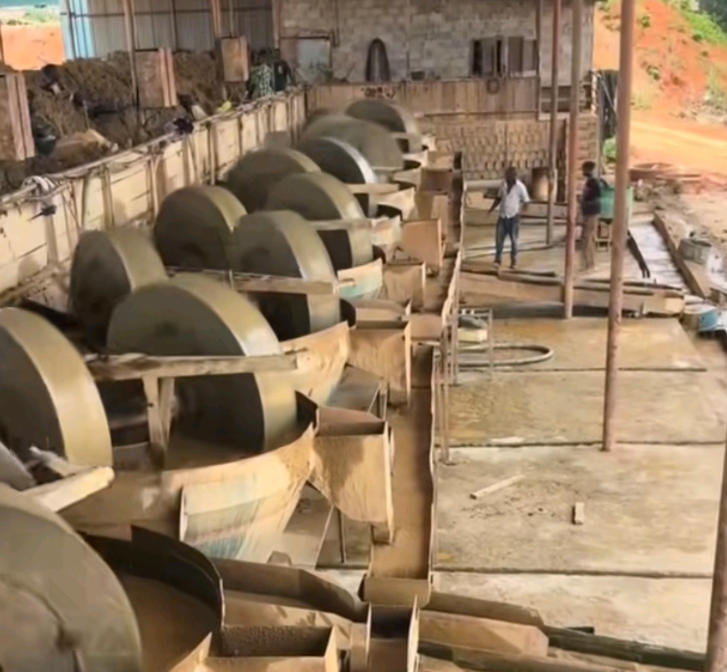
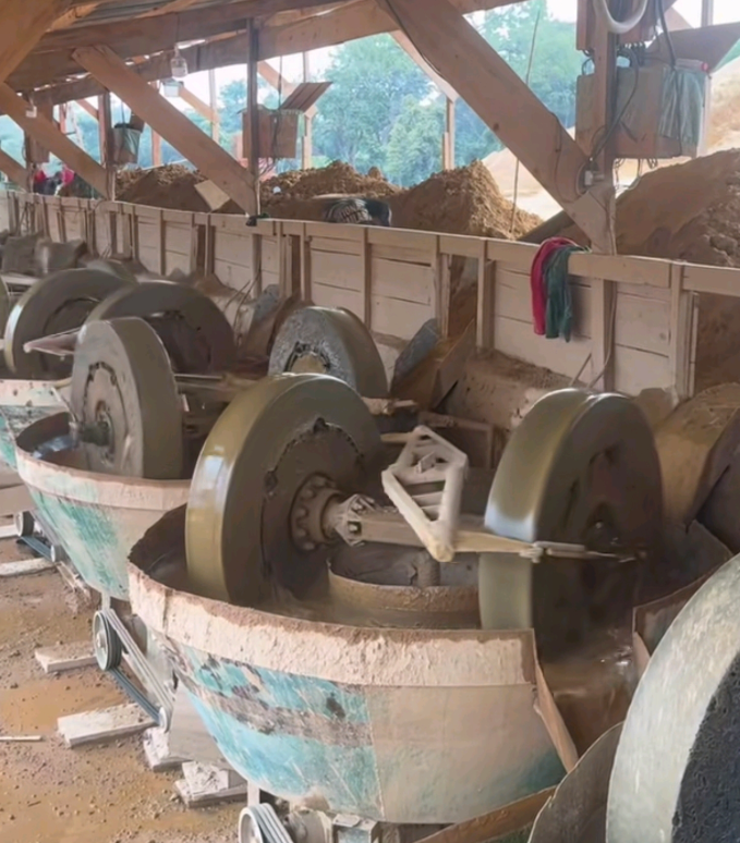
    The wet pan mill: grinding and liberation

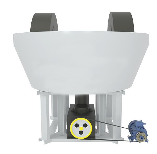
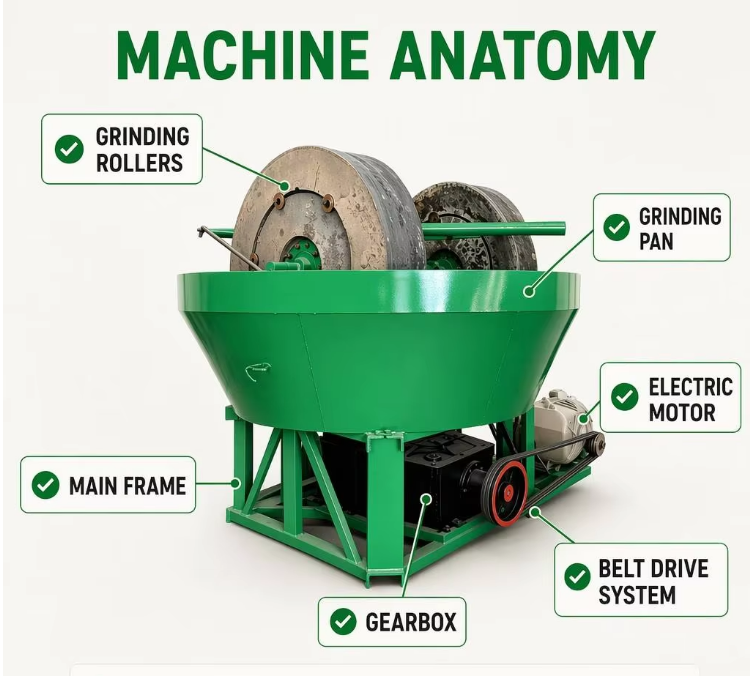
    The mill’s contribution is mechanical. Ore is reduced against the pan by rotating wheels, and gold is freed from its host. On a wet pan mill this happens wet, which keeps dust down and lets the pulp flow straight into the next stage without drying.

    The mill’s output is a slurry — not a concentrate. Everything downstream depends on what that slurry contains.

    The concentrator: catching what the mill releases

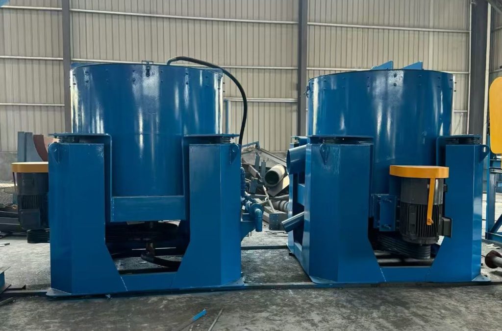
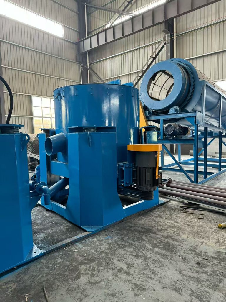
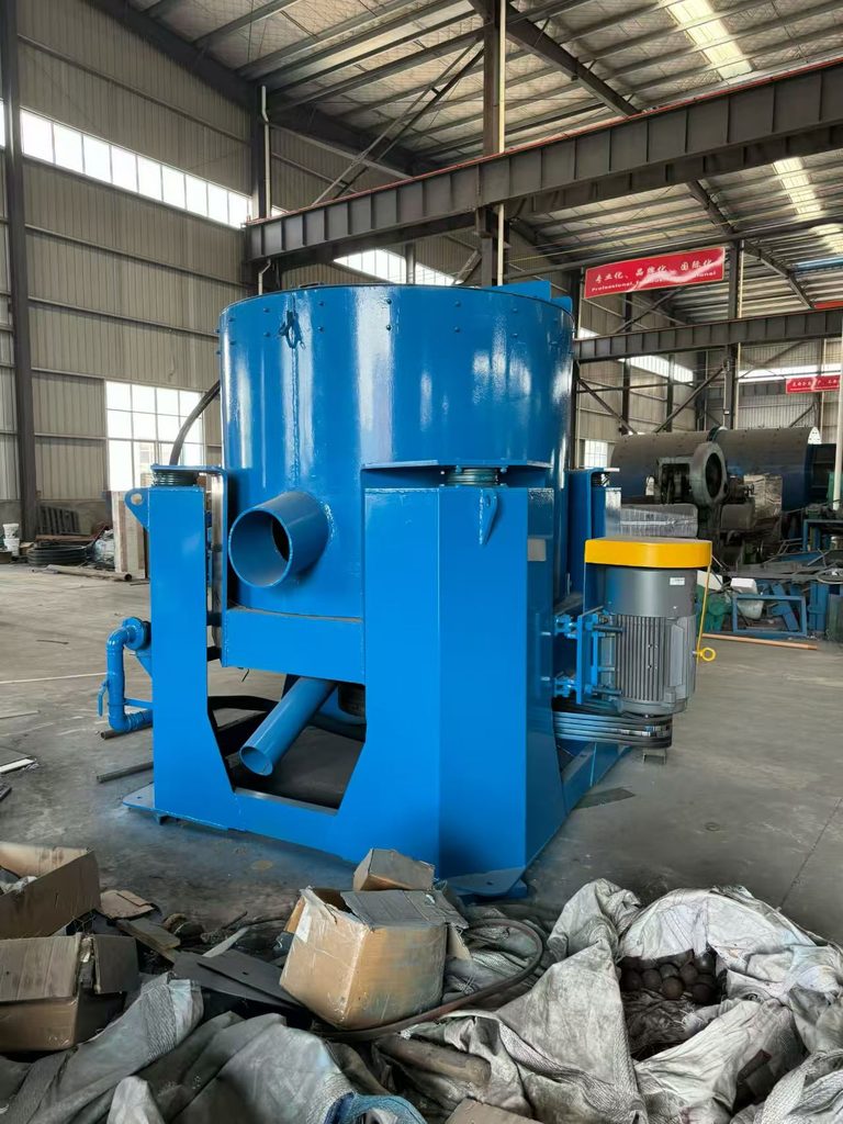
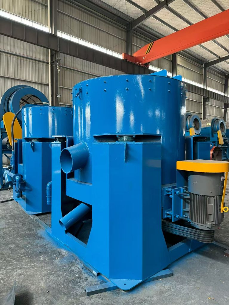
    A centrifugal concentrator takes the mill’s tailings slurry and spins it. Heavy particles — gold, and mercury or amalgam if present — are driven outward and trapped in the bowl’s riffles or fluidised bed. Lighter sand is carried up and out.

    On the STLB series we supply, feed is limited to 6 mm, which in practice means the mill’s discharge usually needs screening or classification before it enters the bowl. That constraint is not a limitation of the method — it is the size at which the fluidised bed can still hold fine gold without packing solid.

    Where the concentrate leaves the bowl

    On a batch concentrator, the split is straightforward: light waste sand exits from the outer discharge, while the heavy concentrate collects at the bottom and is drawn off through the central port at the end of a cycle.

    That geometry is what makes the unit useful for tailings work — you are not trying to recover a salable product in one pass, you are trying to shrink a large volume of low-grade slurry into a small volume of high-grade concentrate that a shaking table can finish.
    How to Run the Pairing

    Feed

    Route the mill’s tailings slurry into the concentrator, but control two things before it arrives: pulp density and particle size.

    Density that is too high turns the feed into a paste that blinds the riffles. Oversize particles — anything above the bowl’s rated feed size — lodge in the bed and reduce capture for everything behind them. A screen or a classifier ahead of the concentrator solves both.

    Concentration

    Inside the bowl, centrifugal force does the sorting. Heavy minerals settle into the collection zone; light sand is flushed out continuously. The unit runs until the collection zone is loaded, then stops for discharge.

    Discharge and recovery

    Concentrate is taken off in batches from the bottom port. If the material contains mercury or amalgam, that handling step is where exposure risk concentrates — it should happen in a sealed, ventilated arrangement, never in the open.

    What the cycle time buys you

    In field practice, operators report that separating mercury from a batch of concentrate by hand can take one to two hours, while a concentrator throws off the water and lighter material in minutes, leaving a much smaller volume to deal with. That time saving is real, but treat the specific figure as an observation from operating sites rather than a universal constant — it depends heavily on batch size and how much amalgam is present.
    Five Things That Decide Whether It Works

    1. Particle size and sliming. Too much fine clay coats the collection zone and blinds it. If your ore slimes heavily, de-sliming or classification ahead of the bowl is not optional.

    2. Speed and centrifugal force. Higher speed increases the force holding fine gold, but it also drags light sand into the concentrate and raises power draw. Too low and the fines simply pass through. The setting has to be tuned against your own ore, not copied from another site.

    3. Backwash water and jacket pressure. Water injected through the bowl keeps the bed fluidised and prevents it from packing. Get it right and fine gold penetrates and is captured; get it wrong and the bed either consolidates or blows through. On water-jacketed units this is the parameter operators adjust most often.

    4. Feed stability. Fluctuating density or flow rate destroys separation. A buffer tank and a consistent feed arrangement matter more than most operators expect.

    5. Maintenance. Worn riffles, scored bowls and blocked ports all reduce capture quietly — the machine keeps running and the numbers drift down without an obvious failure. Regular cleaning and inspection is part of the process, not an afterthought.
    Concentrator vs Shaking Table vs Sluice

    These three are often presented as alternatives. In practice they do different jobs.

    EquipmentStrengthWeaknessBest role
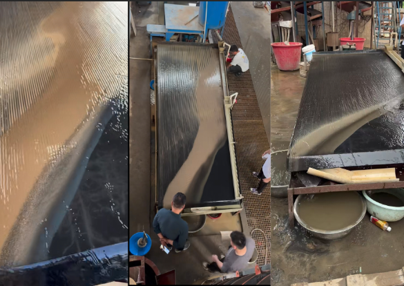
    Centrifugal concentratorFast, compact, strong on fine gold; high volume reductionLower upgrade ratio; concentrate still needs cleaningRoughing and scavenging
    Shaking tableHigh upgrade ratio, stable concentrate gradeLarge footprint; sensitive to feed fluctuationFinal cleaning
    SluiceCheap, simple, low maintenancePoor on fines; high gold loss below ~100 µmCoarse roughing only

    The practical chain is mill → concentrator → shaking table. The concentrator does the volume reduction and catches the fines; the 6S shaking table takes that small concentrate to a salable grade. Running a table on raw mill tailings instead would mean feeding it far more material than it can handle, at a grade too low to separate cleanly.

    If Your Circuit Still Uses Mercury

    A concentrator is often fitted specifically because a site is moving away from amalgamation — the unit recovers the fine gold that mercury was previously used to capture, without the mercury.

    If amalgamation is still in your circuit, the safety points below are not optional.

    The hazard is the vapour, not the liquid. Mercury vapour is acutely neurotoxic and causes cumulative kidney damage. It is released whenever amalgam is heated, and it is odourless — you cannot smell your way to a safe working level.

    Contain it. Amalgamation, pressing and retorting belong inside a sealed, negatively ventilated enclosure with off-gas capture. Open roasting of amalgam — the practice still seen at some small operations — is the single most dangerous step in the process and should never be done in the open.

    Protect and collect. Operators need appropriate respiratory and skin protection. Floors should be sealed and washed routinely, and the site needs dedicated mercury collection and wastewater treatment so nothing migrates into soil or groundwater.

    Expect regulation. Mercury use in artisanal and small-scale gold mining is restricted under the Minamata Convention, and national limits on mercury emissions and occupational exposure are tightening almost everywhere. Operators who build a mercury-dependent circuit today are building something they will have to replace.

    The alternative is already proven: a gravity circuit — mill, concentrator, table — recovers the same fine gold without the exposure, the reporting burden, or the buyer objections. That is why the mercury-free gravity route is now the default recommendation for new installations rather than a niche option.

    Commissioning Checklist

    Before you buy anything, characterise the ore:

    • Size analysis and gold deportment. You need to know what fraction the gold sits in. If most of it is below 38 µm, a concentrator is the right tool; if it is locked in sulphides, gravity alone will not reach it.
    • Test at small scale. Run speed, density and feed-rate trials on your own material and choose the setting on the recovery-versus-grade trade-off, not on a single headline recovery number.
    • Design for containment. If any mercury remains in the circuit, plan sealed handling, off-gas condensation and wastewater treatment from the start — retrofitting is far more expensive.
    • Instrument the circuit. Sample concentrator feed, concentrate and tailings regularly. Drift in tailings grade is the earliest signal that a bowl needs cleaning or a riffle needs replacing.

    Building the Circuit

    If you are running pan mills and losing fine gold to tailings, the fix is usually a concentrator sized to your mill discharge — and a table to finish what it produces.

    Send us your ore type and target throughput and we will size the two-stage circuit around it, or review complete process line designs if you are starting from run-of-mine.

    BLICK Industries builds wet pan mills, STLB centrifugal concentrators and 6S shaking tables in our own factory and ships direct to gold operations
  • 3 Factors That Decide Your Gold Recovery Rate

    Two mines. Twenty identical wet pan mills each. One recovers more than a thousand grams of gold a day — sometimes as much as 1,600 grams. The other recovers less than a thousand.

    Same machines. Same type of ore. A gap that large is never luck. In practice it comes down to three things the operator controls: the size of the ore going in, the speed the mill runs at, and what sits downstream to catch the gold that gets away.

    This article covers all three — and the one limit that no amount of tuning will beat.

    Why Identical Equipment Produces Different Results

    When two operations run the same model and get different numbers, the equipment is rarely the problem. The difference almost always traces back to two things: throughput (how much ore the mill actually processes per hour) and recovery rate (what percentage of the gold in that ore you manage to collect).

    Those two figures are set before the mill ever turns — by how the ore is prepared and by how the machine is run. So the diagnosis starts upstream, not at the mill.

    Factor 1: Control the Feed Size

    The size of the ore you feed the mill determines its workload — and therefore how much ore it can get through in a day.

    For common models like the 1100 and 1200 wet pan mills, keep the raw ore feed within 20–30 mm (two to three centimetres). If the ore is hard, tighten that further to 10–20 mm (one to two centimetres). Cutting the feed size takes a large load off the mill, which shows up directly in throughput.

    Oversized ore should never reach the pan mill. Break it down first with coarse and fine crushing stages, then feed the mill at the size it was designed for. If you are still feeding fist-sized rock straight into the pan, that is the first place to look.

    → Crushing equipment sized to feed your mill

    Factor 2: Get the Mill Speed Right

    The running speed is the single most important operating parameter for recovery — and the one most often set by feel rather than by calculation.

    In the early days of grinding iron ore, a 1.2-metre machine typically ran at around 22–23 rpm. In gold operations, however, some operators worry about gold escaping the circuit and deliberately slow the mill down to 12 rpm, or even 8–9 rpm. That instinct is understandable, but it works against you: a large drop in speed directly reduces how much grinding work the mill performs per pass.

    Aim for roughly 18–20 rpm instead. At that setting you get more grinding passes over the same ore, which improves liberation — and to a degree, throughput as well.

    Slower is not safer. Gold that was never liberated cannot be recovered further downstream, no matter how good your recovery equipment is.

    → Wet pan mills, 1200–1600 series

    Factor 3: Add Recovery Equipment Downstream

    Some gold will always leave the mill still attached to tailings. The way to get it back is to install auxiliary recovery equipment at the right points in the flow — so that material which would otherwise be lost gets a second chance.

    Amalgamation plates

    One or two plates are enough. Initial cost runs about RMB 1,000–2,000, and the plates are reusable — with use, their value can even increase rather than depreciate. A plate adsorbs gold effectively and can be scraped clean, which makes the return on the investment very favourable.

    Amalgamation barrels

    A barrel costs roughly RMB 3,000–4,000. There is some daily consumption to account for, but the gold it recovers is worth far more than the equipment costs, so it earns its place in the circuit as an auxiliary unit.

    Blankets and felt matting

    For flake gold that floats rather than settles, laying down blankets or felt matting gives those particles something to catch on. It is the simplest and cheapest of the three, and it works specifically on the fraction that gravity alone tends to miss.

    → Alluvial recovery equipment — tables, concentrators and sluices

    There Is a Ceiling on Recovery — Know Where It Is

    Recovery has a hard limit, and it is set by the ore itself, not by your equipment.

    Gold in ore occurs as particles of many different sizes and in complex associations. Not every gold particle or gold molecule can be captured by a plate, a barrel or a mat. Some loss is unavoidable in any circuit.

    The practical target is therefore not 100% — chasing that number leads to bad decisions. The target is to push recovery as close to the physical ceiling of your ore as your equipment and parameters allow, and to know where that ceiling sits so you can tell the difference between a real problem and a natural limit.

    Where to Start

    If your recovery is below expectation, work through the three factors in order:

    1. Feed size — get ore down to 20–30 mm, or 10–20 mm for hard rock, before it reaches the mill.
    2. Mill speed — set it around 18–20 rpm rather than slowing it down out of caution.
    3. Downstream equipment — add plates, barrels or matting to recover what the mill cannot hold on to.

    Then set a realistic recovery target based on your ore, and measure against that — not against a theoretical maximum.

    BLICK Industries supplies wet pan mills, ball mills, crushing and gravity recovery equipment to gold operations worldwide, built in our own factory and shipped direct. Tell us your ore type, target throughput and power source, and we will recommend a configuration.

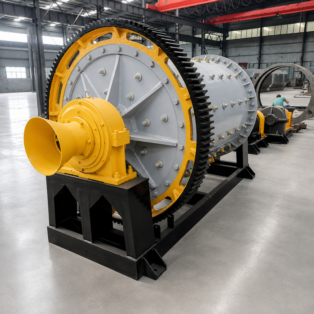
  • How to Control Ball Mill Output Fineness: Dry and Wet Milling

    Why fineness is a window, not a target

    Grinding is the last stage where you can still lose the gold — and the first stage where you can waste the most power. Run too coarse and locked particles travel all the way to the tailings. Run too fine and you pay for energy you did not need, generate slimes that are hard to recover on gravity equipment, and push reagent consumption up in a leaching circuit.

    So the goal is never “as fine as possible”. It is the narrowest size range your downstream process can still recover efficiently. Everything below is about how to move the product within that window — and which lever to reach for first.

    Dry ball mill: five control points

    1. Steel ball grading

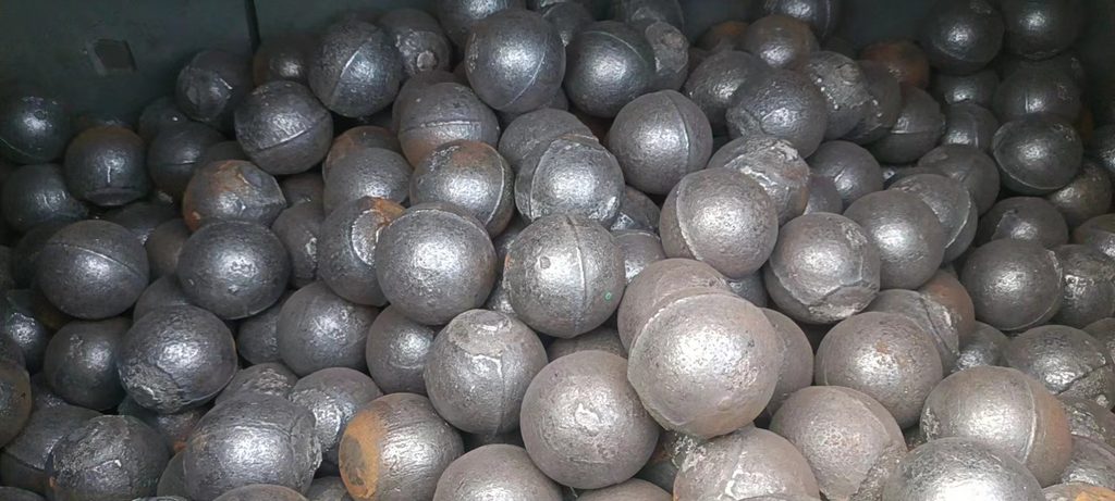
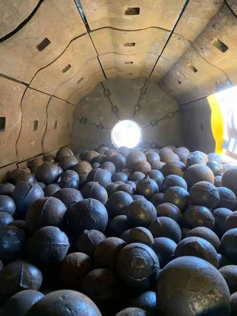
    The media charge decides how the material is ground. If the material leaving the mill is too coarse, the charge contains too many large balls — reduce the large-ball proportion and add small balls. If the material is coming out too fine, do the reverse: reduce the small balls and add large ones.

    2. Mill ventilation (airflow)

    Internal airflow controls how fast material is carried out of the mill. When the discharge is too coarse, the airflow is too high — reduce it. When the discharge is too fine, the airflow is too low — increase the ventilation.

    3. Classifier speed (closed-circuit systems)

    In a closed-circuit grinding system, the classifier is the fineness control point. Higher classifier speed gives a finer finished product; lower speed gives a coarser one.

    4. Feed size entering the mill

    The initial particle size of the feed determines how long the material must stay in the mill to be reduced. Coarser feed takes longer to break down, so the discharge comes out coarser. Finer feed reaches the target size sooner, so the discharge comes out finer.

    5. Partition plate blockage (multi-chamber mills)

    If the discharge gets finer and tonnage drops noticeably at the same time, check the partition plate first. A blocked plate slows material movement through the mill, residence time stretches far beyond design, and the product gets over-ground while output falls — often with reduced moisture removal as well.

    Dry-milling quick diagnosis

    SymptomLikely causeCorrection
    Discharge too coarseToo many large balls in the chargeReduce large balls, add small balls
    Discharge too coarseInternal airflow too highReduce ventilation
    Discharge too coarseClassifier speed too lowIncrease classifier speed
    Discharge too coarseFeed entering the mill too coarseReduce feed size to the mill
    Discharge too fine and output downPartition plate blockedInspect and clear the partition plate

    Wet ball mill: four control points

    1. Pulp density

    Pulp density drives slurry mobility and therefore residence time. A denser pulp stays in the mill longer and the discharge gets finer. A thinner pulp flows more freely, leaves sooner, and the discharge gets coarser.

    2. Ore feed rate

    Feed rate works in reverse against fineness. Push more tonnage through the mill and the discharge gets coarser; cut the feed rate and the discharge gets finer.

    3. Mill rotational speed

    Wet mills are normally fitted with variable-speed drives, so the operating speed can be adjusted within roughly 65% to 75% of critical speed. Increasing mill speed produces a finer discharge; reducing it produces a coarser one.

    4. Classification circuit

    Wet grinding circuits are almost always paired with classification equipment — typically hydrocyclones. The final cut point of the discharge is set by the hydrocyclone and its pump system, not by the mill alone.

    Wet-milling quick diagnosis

    SymptomLikely causeCorrection
    Discharge too coarsePulp density too lowIncrease pulp density
    Discharge too coarseFeed rate too highReduce ore feed rate
    Discharge too coarseMill speed too lowIncrease speed (stay within 65–75% of critical)
    Product unstableClassification circuit out of balanceRe-trim the hydrocyclone and pump settings

    Dry vs wet: which lever actually sets fineness

    Control leverDry millingWet milling
    Media charge (ball grading)Primary controlPrimary control
    Residence timeSet by airflowSet by pulp density and feed rate
    Mill speedUsually fixedAdjustable via variable-speed drive, 65–75% of critical
    Final cut pointClassifier (separator) speedHydrocyclone and pump circuit
    Feed sizeDirectly shifts product sizeDirectly shifts product size
    Fastest useful diagnosticFiner product + lower output → partition plateProduct drifting → density and feed rate

    FAQ

    Why is my ball mill discharge too coarse? Work through the levers in order: ball grading (too many large balls), airflow (too high), classifier speed (too low), then feed size (too coarse). On multi-chamber mills, also confirm the partition plate is clear before changing anything else.

    Why did my product suddenly get finer while tonnage dropped? On a multi-chamber mill this is the classic signature of a blocked partition plate. Material cannot leave the mill fast enough, residence time stretches, and the product is over-ground while output falls. Inspect and clear the plate — do not compensate by adjusting ball grading.

    Does running the mill faster give a finer product? In wet milling, yes. Mills with a variable-speed drive can be run within about 65–75% of critical speed; increasing speed drives a finer discharge and decreasing it gives a coarser one. Dry mills generally run at fixed speed, so use airflow and classifier speed instead.

    Can I control fineness with the hydrocyclone alone? In a wet circuit the hydrocyclone and pump set the final cut point, so trimming them does change the product. But if the mill itself is over- or under-grinding, adjusting the cyclone only moves the problem downstream. Balance the mill first, then fine-tune on the circuit.

    Should I confirm the target size in a lab before tuning? Yes — a bench-scale grind and sieve analysis tells you what the ore actually needs, so you are tuning toward a measured target instead of by feel.

    Set the target size on a test, not a guess

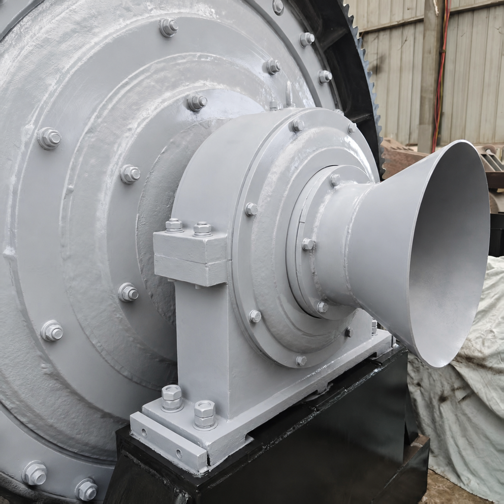
    Tell us your ore type and your target mesh, and we will size the mill, the media charge and the classification circuit as one system. Our MQ series ball mills cover 900×1800 up to 1830×4500, built with energy-saving rolling bearings and replaceable wear liners.

  • Why Your Concrete Block Machine Produces Weak Blocks: 6 Causes and Fixes

    Why Your Concrete Block Machine Produces Weak Blocks: 6 Causes and Fixes

    Weak blocks are the most common complaint we hear from block producers, and the most expensive, because by the time the problem is visible in the yard you have already paid for cement, aggregate, labour, curing and yard space on a batch that cannot be sold.

    The good news is that weak blocks almost always come from one of six causes, and each one has a specific, testable fix. Here is how to work through them in order, from the most likely to the least.

    1. Water content of the raw materials is not controlled

    This is the number one cause, and it is the one producers most often overlook because it is invisible in the finished block.

    Sand and crushed stone arrive with varying moisture. When the moisture in the aggregate goes up, the exact same mix recipe produces a wetter, softer mix. More water means the blocks have higher porosity after curing, and porosity is the enemy of compressive strength.

    Symptom: The same recipe produces good blocks one day and weak blocks two days later, with no change in machine settings.
    Fix: Measure aggregate moisture at least twice per shift and adjust the water addition accordingly. If you are still measuring by feel, that is the problem. A moisture meter pays for itself within a month.

    2. Cement content is being judged by volume, not by weight

    Batching cement by volume — by counting sacks or by bucket — introduces large errors. Cement that has been stored in humid conditions compacts and settles, so the same volume contains more cement than fresh material, or less if it has partially set.

    Symptom: Block strength varies between batches made from different deliveries of the same nominal cement quantity.
    Fix: Batch cement by weight. On a concrete batching plant this is automatic; on a manual or semi-automatic line it means using a proper weighing scale rather than a volumetric measure. Accuracy of ±1% is achievable and is what the mix design assumes.

    3. Aggregate grading is wrong

    Strength comes from a dense, well-graded aggregate skeleton. Two opposite failures cause weak blocks:

    • Too much fine material — excessive dust or clay in the sand increases surface area and therefore the water demand, so cement is effectively diluted.
    • Gaps in the grading curve — if you are using a single coarse aggregate with no intermediate sizes, the voids between large particles never get filled. The block has internal empty space by design.

    Symptom: Blocks feel heavy but break with a rough, granular fracture and visible voids.
    Fix: Run a sieve analysis on your sand and stone. Then either blend two or three aggregate fractions to close the grading curve, or change your sand source. Also wash or screen out excess clay — clay does not just dilute the mix, it physically interferes with the cement hydration bond.

    4. Insufficient compaction in the mould

    A block machine does not cast blocks; it compacts a very dry mix under vibration and pressure. If the compaction energy is too low, the block contains air that should not be there.

    Typical causes:

    • Vibration time set too short to increase output
    • Mould fill weight reduced to save material
    • Worn vibration motor mounts, so the vibration is no longer transferred efficiently into the mould
    • Worn or misaligned mould liners, creating an uneven fill

    Symptom: Block density varies from one end of the pallet to the other, or the top corners crumble.
    Fix: Restore the original vibration time and fill weight for a trial batch, then compare density and 7-day strength. If the machine cannot hold density even at the correct settings, service the vibration system and check the mould wear. Worn moulds are the single most common machine-side cause of strength loss on an older line — see the machine options on our brick making line page.

    5. Curing is too short, too dry, or too cold

    Curing is where concrete develops its strength, and it is where producers cut corners because it costs time and yard space. Cement does not dry — it reacts with water. If the block loses its moisture too early, the reaction stops and the block never reaches its design strength, no matter how good the mix was.

    Symptom: Blocks test well at 3 days but plateau early, and never reach their target 28-day strength.
    Fix: Keep blocks damp and shaded for the full curing period. Practical measures that matter:

    • Cover the pallets with plastic sheeting or cure in a chamber rather than leaving them in direct sun and wind.
    • Water the blocks on a schedule, or use a mist system. Do not soak them cold — avoid thermal shock.
    • Extend curing time in cold weather, and never let blocks freeze while green.
    • Do not move green blocks early to free up yard space. The first 24 hours matter more than any other period.

    6. Machine wear and mixer inconsistency

    If the mix design and curing are correct but strength still drifts, look at the mixing and forming equipment:

    • Worn mixer blades and liners — mixing efficiency drops, and the same mixing time no longer produces the same homogeneity. Partially mixed dry mixes are the classic source of random weak blocks.
    • Inconsistent discharge — mix that segregates as it leaves the mixer gives you blocks that differ from the first pallet to the last.
    • Worn moulds and liners — dimensional wear reduces compaction and changes the density the block can reach.

    Fix: Replace mixer wear parts on an interval based on tonnage produced, not on appearance. Log mixing time and verify it is actually being achieved on every batch — on automatic lines this is measurable; on manual lines it is often the silent variable.

    How to diagnose this systematically instead of guessing

    Do not change five things at once. Work in this order and measure after each step:

    1. Test the compressive strength of a current production batch at 7 and 28 days. You need a baseline figure, not an opinion. A lab press or even a certified third-party test saves money by ending the guesswork.
    2. Record aggregate moisture for three consecutive days alongside those strength results. This alone identifies cause 1 in most plants.
    3. Verify cement is being batched by weight, and check the calibration of the weighing system.
    4. Run a sieve analysis on the aggregates.
    5. Only then start touching machine settings, one at a time.

    If you are choosing equipment for a new line, or replacing a machine that cannot hold density, compare the specifications and the vibration and compaction systems on our fully automatic brick making line and concrete batching plant pages. Compaction capacity and batching accuracy are the two specifications that most directly determine block strength.

    A note on curing temperature

    If you produce blocks in a hot, dry climate — common across the markets we supply — curing is where most strength is lost, and it is the cheapest thing to fix. A simple shade structure and a watering schedule routinely lift 28-day strength by a meaningful margin on the same mix design. Before you spend money on a new machine, spend a week proving that your current curing regime is actually being followed.

    If you send us your mix design, aggregate grading and current 28-day test results, our engineers will tell you which of the six causes is most likely in your plant, and what to change first. Send us your production data here.

  • CIL vs CIP: Which Gold Leaching Process Fits Your Ore?

    CIL vs CIP: Which Gold Leaching Process Fits Your Ore?

    CIL and CIP are the two standard processes for extracting gold from ore using cyanide and activated carbon. They sound similar, they are often quoted interchangeably by suppliers, and choosing the wrong one for your ore will cost you recovery for the entire life of the plant.

    This article explains the real difference between them, when each one wins, and what you should test before you commit.

    The one difference that matters

    Both processes do the same two things: dissolve gold into cyanide solution (leaching), and then pull that gold out of solution onto activated carbon (adsorption). The difference is where adsorption happens.

    • CIL — Carbon In Leach. Activated carbon is added directly into the leach tanks. Leaching and adsorption happen simultaneously in the same vessels. Gold is dissolved and captured on carbon almost immediately.
    • CIP — Carbon In Pulp. Leaching happens first in a separate train of tanks. Only after leaching is complete does the slurry move to a separate adsorption train where carbon is added.

    That is the whole architectural difference. Everything else — tank sizes, carbon transfer systems, desorption, electrowinning, regeneration — follows from it.

    Why the difference changes your recovery

    Because CIL adsorbs gold as soon as it dissolves, the gold concentration in solution stays very low throughout the leach. This matters enormously for a certain class of ores.

    Preg-robbing ores — ores containing carbonaceous material, graphite, or certain clay/shale components — actively adsorb dissolved gold onto themselves instead of letting it stay in solution. In a CIP circuit, the gold that gets robbed onto the ore is simply lost with the tailings. In a CIL circuit, the activated carbon competes for the gold and usually wins, because it is present from the first tank at high concentration.

    If your ore is preg-robbing, CIL is not a preference — it is the difference between a viable project and one that loses a large share of its gold.

    Where CIP still wins

    CIP is not obsolete. It has real advantages on the right ore:

    • Cleaner control. Because adsorption has its own dedicated train, the carbon advance rate, carbon concentration and elution schedule can be optimised independently of the leach conditions. On a clean oxide ore, this often produces a slightly higher overall recovery and a more consistent carbon loading.
    • Simpler chemistry. Reagents are added to a leach circuit that contains no carbon, so less cyanide is adsorbed and consumed by the carbon itself.
    • Better for high-silver ores in some cases. Silver behaviour on carbon differs from gold, and a separate adsorption train can give more flexibility in managing it.
    • Lower carbon attrition in some configurations — carbon spends less time in high-shear, high-solids leach tanks.

    In practice, most modern gold plants that handle a mix of ore types are built as CIL, because it is more forgiving. CIP is typically chosen when test work shows the ore is clean and requires no preg-robbing protection.

    Side-by-side comparison

    Factor CIL CIP
    Where adsorption happens In the leach tanks In a separate adsorption train
    Gold in solution during leach Kept very low Builds up to a normal leach profile
    Preg-robbing ore Handles it Loses gold to the ore
    Tank count for the same throughput Fewer, because leach and adsorption are combined More, because both stages need their own tanks
    Process control flexibility Lower, but more forgiving Higher
    Typical application Mixed and difficult ores, most new projects Clean oxide ores with completed test work

    What you must test before choosing

    The choice should never be made on ore type description alone. Before committing to CIL or CIP, you need:

    1. Bottle roll or leach tests at your target grind size, to establish the achievable gold extraction and the reagent consumption.
    2. A preg-robbing test — a carbonaceous matter assay plus a comparative leach with and without carbon present. This is the single most important test, and the one most often skipped.
    3. Grind size optimisation — finer grinding liberates more gold but consumes more power and can create more preg-robbing fines. The optimum is ore-specific.
    4. Carbon activity and attrition testing — to size the carbon inventory and predict make-up consumption.
    5. Settling and viscosity tests — clay-rich ores can make slurry handling and carbon screening difficult regardless of which process you choose.

    These tests need very little material and can be run before you commit capital. Doing them in the wrong order is how projects end up rebuilding their leach circuit two years after commissioning.

    What comes after the leach circuit

    Whichever process you choose, the back end of the plant is essentially the same, and it is where projects are most often under-sized:

    • Desorption (elution) — stripping the gold off the loaded carbon, usually by the Zadra or AARL route depending on scale.
    • Electrowinning — recovering the gold from the pregnant eluate onto steel wool or plates.
    • Carbon regeneration — thermal regeneration in a kiln to restore carbon activity. Under-sizing this kiln is a common and expensive mistake, because it forces you to keep buying fresh carbon.
    • Smelting — producing the final doré bar.

    Get the regeneration kiln capacity right at the design stage. It is far cheaper than adding capacity later.

    How plant scale changes the answer

    Small plants and large plants do not make the same choice. At the smaller end of the range — tens of tonnes per day — CIL with a small number of combined leach-adsorption tanks is usually the practical option, because it needs the fewest vessels and the least instrumentation. As throughput grows into the hundreds of tonnes per day and beyond, the extra tanks of a CIP train become an affordable way to buy process control, provided the ore permits it.

    If you want to see how the equipment is arranged at each of these scales, our CIP / CIL production line page lists standard configurations by daily capacity, from 50 t/d up to 1,000 t/d.

    The three mistakes that cost the most

    1. Choosing CIP without a preg-robbing test. The mistake that destroys projects. If the ore robs carbon, no amount of operational skill will recover the lost gold.
    2. Under-sizing the desorption and regeneration circuit. The leach tanks get all the attention; the back end gets skimped. The result is a plant that cannot keep up with its own loaded carbon.
    3. Designing for a grind size you cannot achieve. Test work at 75 microns is meaningless if your mill circuit cannot consistently deliver it. Match the flowsheet to your grinding circuit, not the other way around.

    Next step

    If you are at the design stage, send us your ore test results — extraction percentage, reagent consumption, grind size, and whether any preg-robbing behaviour was observed. We will tell you which process fits and give you a tank arrangement and equipment list for your target capacity.

    If you have not run the tests yet, we can supply the laboratory equipment to do the work at site scale before you commit to a full line.

    Get in touch with our process engineers here and we will come back with a configuration and a budget figure.

  • How to Choose a Gold Shaking Table for Alluvial Mining

    How to Choose a Gold Shaking Table for Alluvial Mining

    If you are building or upgrading an alluvial gold plant, the shaking table is usually the last piece of equipment that decides how clean your concentrate is — and how much you lose to the tailings. It sits at the end of the gravity circuit, after the trommel scrubber, the screen and the centrifugal concentrator, and its job is simple to describe but hard to do well: separate gold from heavy sand using nothing but water, a riffled deck and a slight sideways shake.

    This guide covers what actually determines whether a shaking table works on your ore, and how to specify one without over- or under-buying.

    What a shaking table actually does

    A shaking table is a gravity concentrator. Slurry is fed across a slightly tilted, riffled deck that is shaken along its long axis. Three things separate the particles at the same time:

    • Density difference — gold (specific gravity around 19) settles into the riffles while quartz and sand (around 2.6) wash over them.
    • Particle size — finer particles travel further than coarse ones under the same water flow.
    • Water film — the cross-flow of wash water carries the light material off the lower edge while heavy minerals stay trapped.

    Because the table works on density and size, the size range you feed it matters enormously. This is the single most common source of disappointment with shaking tables.

    Step 1: Match the deck type to your feed size

    Shaking tables are built with different riffle profiles for different size bands. A 6S-type table is normally supplied in three deck variants:

    Deck type Typical feed size Use it when
    Coarse sand deck Roughly 0.5–2 mm Concentrate from a jig or rougher table, coarse alluvial gravel fractions
    Fine sand deck Roughly 0.074–0.5 mm The most common choice — typical alluvial sand after screening
    Slime deck Below roughly 0.074 mm Fine material recovered from settling ponds, overflow and tailings

    If you feed a deck material it was not designed for, you lose gold. Feeding coarse sand to a slime deck overloads the riffles and flushes gold out with the tailings. Feeding slime to a coarse deck gives you almost no recovery, because the fine particles simply wash across the riffles without settling.

    The practical rule: classify before you tabulate. Screen the feed into at least two size bands and run each band on the correct deck, or accept a lower recovery.

    Step 2: Work out how many decks you need

    A single deck handles a modest throughput. Producers who need to process a continuous concentrate stream usually run several decks in parallel rather than one large table, because the separation quality depends on a thin, evenly distributed bed of material — you cannot simply scale a table up by making it wider.

    To size the circuit, you need three numbers:

    • Your concentrate feed rate in t/h entering the table circuit (not your total plant feed — the table only sees the concentrate from the upstream rougher stage).
    • The size distribution of that concentrate, so you can allocate decks correctly.
    • Your target concentrate grade, which determines how many cleaning passes you need.

    A typical arrangement is a rougher table followed by one or two cleaner tables, with the cleaner tailings returned to the rougher feed. This middlings recirculation is what turns a mediocre recovery into a good one.

    Step 3: Check your water supply before you order

    Shaking tables are thirsty. They use wash water continuously across the deck, and the flow rate has to be adjustable, because the correct wash water setting changes with feed size, feed rate and grade.

    If your site has limited water, plan for:

    • A settling pond and return pump, so the wash water is recirculated rather than lost.
    • A head tank with a constant level, feeding the table through an adjustable valve. Gravity-fed wash water with a stable head is far easier to control than a pump running at variable pressure.
    • Consistent feed density. A slurry that surges thick and thin will ruin the separation no matter how well the table is adjusted.

    Where the table fits in the alluvial flowsheet

    A well-designed alluvial plant recovers gold in stages, with each stage handling a narrower size band and a higher grade:

    1. Trommel scrubber and screen — breaks up clay and separates the gravel from the sand. Washing quality here decides how much fine gold is available for recovery downstream.
    2. Centrifugal concentrator — takes the screened undersize and recovers a large share of the free gold, including fine particles, at high upgrade ratios.
    3. Shaking table — cleans the concentrator product and gives you a final gravity concentrate that is low in volume and ready for smelting or further upgrading.

    If you are not yet recovering the fine fraction of your feed, the table is not the first thing to fix — the washing and screening stage is. See the equipment options on our alluvial gold equipment page and our trommel and washing systems page.

    Common mistakes that cost recovery

    • Feeding unclassified material. The most frequent error. One table cannot separate 3 mm gravel and 30 micron slime at the same time.
    • Uneven feed. A fluctuating slurry density changes the bed depth on the deck and destroys the separation. Use a steady head tank, not a direct pump from a pit.
    • Running too fast to chase tonnage. Increasing the stroke or feed rate beyond the deck’s capacity looks productive and loses gold. Recovery on a table is inversely related to throughput.
    • Ignoring wash water adjustment. The wash water valve is a control, not a setting. It needs adjusting as feed grade changes.
    • Skipping the cleaning pass. A rougher-only table typically produces a concentrate that still needs smelting or a second pass to be saleable.

    Maintenance that actually matters

    Shaking tables have very few wearing parts, but the parts that do wear directly affect recovery:

    • Riffles and deck surface — worn or bent riffles change the flow pattern. Inspect and replace as a set.
    • Head motion bearings — the eccentric drive needs clean lubrication and a check for play. Excess play shows up as inconsistent stroke.
    • Deck support — the deck must sit level side to side and at a consistent slope end to end. A knocked support changes the tilt and the separation.

    What to tell a supplier before you buy

    If you send a supplier the following, they can size the table circuit correctly on the first attempt instead of guessing:

    1. Feed size distribution of the material entering the table (sieve analysis if you have it).
    2. Feed rate in t/h and slurry density.
    3. Grade of the feed and the grade you need in the concentrate.
    4. Available wash water flow rate, and whether it can be recirculated.
    5. Site conditions: power supply, floor area, ambient temperature if it freezes.

    If you are not yet sure what your concentrate grade will be, a small lab-scale gravity test is worth doing before committing to a full-size circuit — see our laboratory equipment page.

    If you already know your feed and target, send us the numbers and we will recommend the deck types, the number of units and the flowsheet around them. Send us your ore data here and our engineers will come back with a configuration.